Monday, July 30, 2018

Fast Active Directory Replication and Change Notification

This setting also can affects the Bridgehead settings for AD (please refer to my post on Bridgehead settings). Active Directory site links have three key attributes governing efficiency: schedule, cost, and interval. They also have a feature called “change notification” that is not exposed in the GUI. The table below summarizes defaults versus today’s recommended practices:

Default
Recommendation
Schedule
24 x 7
24 x 7
Cost
100
100 *
Interval
180 minutes
15 minutes
Change Notification
Disabled
Enabled *
* Tweak as appropriate.
Active Directory Topology should be looked at when the organization is looking at making changes to departments, adding or removing locations and as an overall ongoing audit to ensure what was implemented matches what was designed. The is a free tool will draw a Visio diagram of your sites and links. 

A useful tool Microsoft Active Directory Topology Diagrammer can be helpful for auditing your AD site topology to keep what was implemented to the intended design. Continuously verifying your AD can help ensure that major changes are planned out and implemented correctly; not hastily.

To implement Change Notification:
Open ADSI Edit the Configuration Server (not shown below)


If your missing the Configuration Server from your list; you need to make a new connection for the configuration: Right Click on ADSI Edit and Select Connect

The Following popup will come up. On Connection Point press the second radio “Select a well-known Naming Context:”

Select “Configuration” from the Dropdown menu


Hit OK
Once that is done browsse though Configuration -> CN=Sites -> CN=Inter-Site Transports -> CN=IP and click on CN=DEFAULTIPSITELINK and right click and select properties as shown below.

To Enable change notification you have to add the value 1 to the “options” option. Now if you can’t find the “options” option it would be because of the filter settings in ADSI Edit.


By Default the “options” option blank and the default value is setup to only display attributes that have values.
You need to uncheck the “Show only attributes that have values” and then you can find the “options” setting and set it to 1.


Then Hit Ok and Apply. Now we need to make 2 registry entries to enable change notification on our AD controllers.

Option Value = 1 -> Change Notification with Compression

Option Value = 5 -> Change Notification with no Compression


On our AD controllers we need to add 2 registry (Dword32) key entries.  If they are not there add them.

HKEY_LOCAL_MACHINE\SYSTEM\CurrentControlSet\Services\NTDS\Parameters

Replicator notify pause after modify (secs)

set to 15 seconds (tweaking may be required based on infrastructure)

and

Replicator notify pause between DSAs (secs)

set to 3 seconds (tweaking may be required based on infrastructure)


References:

http://pctechgo.blogspot.com/2014/03/active-directory-intersite-replication.html
https://blogs.technet.microsoft.com/qzaidi/2010/09/23/enable-change-notifications-between-sites-how-and-why/
https://blogs.technet.microsoft.com/ashleymcglone/2011/06/29/report-and-edit-ad-site-links-from-powershell-turbo-your-ad-replication/
https://blogs.msdn.microsoft.com/canberrapfe/2012/03/25/active-directory-replication-change-notification-you/
https://blogs.technet.microsoft.com/markmoro/2011/08/05/you-are-not-smarter-than-the-kcc/

Tuesday, July 24, 2018

Active Directory Bridgehead Settings

Back in May I did a post about doing my organizations AD Health and Security Audit. Well now is the start of that process (wish me luck so I don't break anything). I had setup a mirror to lookup errors and verify that processes are going to work but a lab environment can really only take you so far. So today I began the process of going through the Active Directory will be going though the bridgehead settings in Active Directory.

The bridgehead in the domain were setup like this

Domain's Previous Bridgehead settings
This means that AD02, AD1 and Mission were preferred Active Directory Replicators and AD00 would have a harder time replicating changes (but not impossible) since it is not a preferred AD Controller. This would be consistent with other IT staff making changes on AD00 and changes were being replicated properly and/or extremely slowly if not at all. 

To make these changes we need to get the properties of the servers defined as bridgeheads and remove the IP protocol from the specified bridgehead setting.

Server's Bridgehead settings before
According to my research Bridgehead servers are domain controllers that have replication partners in other sites. The selection of bridgeheads is automatic by default. Manually defining preferred bridgeheads is generally not required, because it incurs additional administrative overhead, can reduce the inherent redundancy of Active Directory, and can easily result in replication failures due to invalid configurations.

Designating a single bridgehead for a domain in a site that contains a single domain controller of that domain is redundant as that domain controller would have been the bridgehead anyway. It can also lead to future problems should additional domain controllers be deployed to the site and only one of them configured as a preferred bridgehead server

Now since this is a single AD site and everything is local there is no need to manually set a bridgehead server.


When is it appropriate to manually specify a bridgehead server?

Since we know a bridgehead server is a domain controller (DC) that functions as the primary route of Active Directory (AD) replication data moving into and out of sites it is best used in low bandwidth situations. This setup would minimize bandwidth usage during intersite communication; the Knowledge Consistency Checker (KCC) would dynamically choose a server from each site to handle the communication.

These servers would be the bridgehead servers so rather than letting the KCC choose the servers; you might prefer to nominate domain controllers (e.g., a domain controller with the best network connectivity, a domain controller that is the proxy server in a firewall environment).  For more information about the replication transport protocols over site to site visit the How Active Directory Replication Topology Works Document by Microsoft

IP Transport has been removed from the Bridgehead
The bridgehead servers have now been setup to be automatically selected by the KCC and because this is a single site where everything is local these settings should now be sufficient and stop some of the issues when we makes changes to the AD on any controller and have it replicate though.

Tuesday, July 17, 2018

Configuring High Availability for Windows Server and a FreeNAS iSCSI target using Cisco Meraki Switches


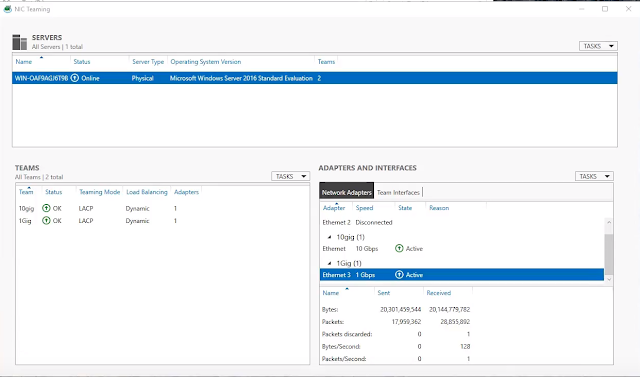
This post will go over how to setup a 10 gig link with a 1gig failover between Windows and FreeNAS using a Cisco Meraki Stack.  The FreeNAS Server is setup using a FAILOVER link aggregation which allows the FreeNAS Server to keep it's IP address in the event of a switch or link failure.  The Meraki Stack has the Windows Server setup for LACP for aggregation on port 1 on 125.46 and port 24 on 125.47.  FreeNAS is set up for LACP for aggregation on port 1 on 125.27 and port 24 on 125.46.  LACP automatically disables the slower port and it is used in a FAILOVER mode as shown in the image below.

Meraki Stack Setup


The Windows Connection is setup as two different network interfaces with 2 different IP addresses.  As shown in the image below there is a 10 gig network interface and a 1 gig network interface.  These interfaces cannot be aggregated together, if you do they will not operate properly.
Windows Network Interface Setup


FreeNAS Network Setup For FAILOVER aggregation

The Windows Server for the Hyper-V Server or just as the host has actually two different IP addresses as stated before.  This should not be a problem if your using it as a Hyper-V host as the VM's that you are running will get it's traffic from the failover connection should the primary connection fails.


Before our failover here are some benchmarks of our FreeNAS connection using the iSCSI Connector


As you can see we are pretty much saturating the network bandwidth of the 10gig link, and now when we cause a failure (in this case I disconnected the 10Gig link) the Storage hesitates for a few seconds before re-routing the network traffic through the failover link.


Windows Showing a failure in the 10 gig link


Once the failure in the link is auto detected port 1 on 125.47 is no longer disabled in the Meraki Stack and the server continues to operate as it should just at a reduced capacity and performance.


The Meraki enables the 1gig link to allow network traffic to continue to flow to the iSCSI target


The Windows server and FreeNAS continue to operate and communicate with eachother but in a reduced capacity until the primary 10 gig link can be restored.

When failing the link back there is no noticeable interruption that I was able to notice from Windows, FreeNAS or the switches.  The only noticeable interruption was when the failure occurred and I doubt it would be noticeable unless it was some application that need to work in real time.  During the failover I wouldn't even call the event a hiccup it went that smooth.  My testing included killing the power from an entire switch in the stack, and killing each link on both switch on both servers.

I must say I was really very impressed by how well the failover worked and I can't wait to get this setup into our production environment.


Approving, Adding and Removing Apps using the Faronics Deep Freeze MDM for Android

This post will go though how to Approve, add and remove apps to your android device using the Faronics Deep Freeze MDM

1. Login to the Deep Freeze MDM


2.  Go to MDM -> Apps


3. If you have approved apps they will be listed as shown below. To approve new apps select add apps


4. This will open up a google play store. Here you can browse or search for apps you want to approve.


5. Select the app you want to approve (in this example MS Word)


6. Press the approve button to approve the app. You will get additional messages about permissions for the app


7.  When finally get through the prompts you will have to choose an option when approving apps. You will want to select the first one, as it allows for the device to be updated. The other option you will have to login to the MDM to approve the updates in the app


8.  With the App now approved (or if it doesn’t show up right away use the “Sync” button beside the add apps button. You need to add the app to a group to install and maintain the app


9.  In the groups select the group you want to add the app to. In this case “test group”


10.  Select the Apps Tab and check the apps you want to apply (install) to the group devices


11.  Then hit save located next to the group name


12.  It could take up to 10 minutes for the devices to sync and apply the settings you have changed. You can do a forced sync by going to Devices -> select the device you want to apply and press the Push Assigned Apps button.


13.  Go to Devices -> Select the device you want to work with and I would recommend adding the TAG for the group and a tag for the name/number of the device.  Faronics MDM doesn't seem to keep the names of the device. 


Friday, July 13, 2018

Setting up Android on Feronics MDM


I've been working on setting up android devices on an MDM. My organization has a Meraki subscription but it is quite pricey compared to using Google, or Deep Freeze. At first I tried to setup Google Admin for managing the devices but it requires to much manual input from users for applying updates. It also affects how BYOD acts when connected. My organization has a subscription to Deep Freeze Premium, which also looks like it has MDM capability. So after briefly doing some configuration on our Meraki MDM, we thought we would give the Deep Freeze MDM a try as it was only 1/3 the price of the Meraki MDM per device.

The Process for setting up the Google Apps with a third party EMM (Enterprise mobility management) is the same, whether it is Cisco Meraki or Faronics Deep Freeze.  You can view my Setup Video on my YouTube Page Here.  The setup for setting up the Deep Freeze MDM is pretty simple, but I had gone though some documentation from Cisco for their Meraki MDM which was really useful for understanding the process for the Deep Freeze MDM.


I highly recommend reading them.
https://documentation.meraki.com/SM/Deployment_Guides/Android_Enterprise_Deployment_Guide
https://documentation.meraki.com/SM/Device_Enrollment/Android_Enrollment

Google Account Management

Managed Google Play eliminates the need for users to use personal Google accounts—it simply uses the same managed accounts that are used for Android enterprise.

If an organization happens to use G Suite, then the users will already have managed corporate Google accounts. For everyone else, EMM vendors can create managed Google Play accounts on the fly—they offer no personal customization, they’re there purely to facilitate application management.

Gsuite Account Management

You need a user account
Google Device Policy App

Setting up the managed play store is much simpler then with a GSUITE account especially with the lack of user account and the generic nature of the the Managed Play Store setup which is what we wanted.

Login to your Google Apps Account go to security


Scroll to Manage EMM Provider for Android

Click on Generate Token

Then login to your MDM provider.  Select your enrollment type (In this case I want Managed Play Store Account)


Click through and enroll.


And your android devices are now managed by your MDM (In my case Faronics)

Friday, July 06, 2018

How to Fix/Setup Teaming and VLans while using Hyper-V on Server 2012, 2012R2 and 2016


If you want to see my youtube video on this post you can view it here.
I've recently had an issue where I got an error getting Vlan and teaming info from the Intel network driver I had installed on server 2012R2.  I had a similar issue back in September of last year with Server 2012 where I couldn't edit, view, add or remove vlans on my Windows 2012 Server.  This month I all of a sudden got an error on almost all our Server 2012R2 systems.  The error is "Get Team Info Failed" as shown below.  


After doing some research and finding this post by Intel about a similar issue; I came across this post which was published in October of 2017 showing how Intel expects you to setup network teaming and Vlans in Windows Server.  Previously our organization setup the all teaming and vlans in the Intel driver as shown below.


Intel Teaming Setup in the Intel Driver


List of Vlans in the Intel Driver
Setting up our nic teaming and vlan networks this way we were susceptible to our settings getting corrupt, over written, moved, or just missing https://www.intel.com/content/www/us/en/support/articles/000007376/network-and-i-o/ethernet-products.html

There is no error or performance difference that I can tell when the driver gets corrupted or missing except when you want to add/edit/remove vlans or edit the teaming on the adapters.  As displayed in the settings below.


Intel Driver Settings


Intel Team Settings on Corrupt/Missing Driver


Settings on Corrupt/Missing Driver


Vlans on Missing/Corrupt Driver.

The way Intel recommends the driver gets setup in Windows is significantly different and since we are using Intel networking hardware I have changed our setup for the servers following Intel's documented setup for Windows Server.  Now since this happened on our production servers, it was a bit tricky to get it changed over to the Intel documented setup.

STEP 1:  First thing we need to do is make sure no one and no service is using the server at the moment, so we will want to pause any backup jobs and either shutdown or move off any VM's running on the server where we are making these changes.  For expediency I recommend downloading the latest Intel drive and keeping it somewhere accessible, as well as documentation with how your server is connected to your switches so you can specify your Native Vlan and any associated tags.


STEP 2:  In Hyper-V (if running) go to the virtual switch manager and set all of your virtual switches to private network.  This will disassociate the switch from any setup VLANs on the host and will allow you remove and update the driver.  Be sure to apply the settings once all your networks have been changed.


Virtual Switch Manager - Setting to Private will allow you to remove and update your intel network driver.
STEP 3:  Remove/Upgrade the Intel network driver (if applicable)


Remove and Update Drivers if Applicable.

STEP 4:  Setup Teaming on your Hyper-V Server

Go to your local server manager and where NIC Teaming is Disabled, click on the Disabled Text.


Enable NIC Teaming by clicking on the Disabled Text


Before creating your team you will want to read this post from Microsoft about the Teaming and Load Balancing Features in windows server to best decide what you will need for your Teaming configuration.  For my purposes I am using a two port LACP LAGG with Dynamic load balancing.

If you have more then one interface/adapter select the ones you want to team and by either shift or Ctrl clicking the interfaces/adapters then from the Tasks menu select Add to New Team

Select the network adapters you want to team and select add to team under the task menu

Now with your team created you can add your VLANs.  You need to select your team in the Teams box on the left of side then under Tasks select Add Interface


Add VLAN interfaces by selecteing the Team and under tasks select Add Interface

This will come up with your settings for your default interface.  This will be your specified Untagged VLAN in your network switch.


Vlans are tied to the Microsoft Multiplexor Driver. 
The more networks you make the Multiplexor driver will auto increment.

As you add more VLANs you will need to specifiy the VLANS your adding by selecting Specific VLAN and inputing the VLAN number.  The Vlan is tied to the Microsoft Network Adapter Multiplexor Driver.  As you add VLANs the number of the Multiplexor Driver will Auto Increment up.  So if you added VLAN 500 the Multiplexor Driver will be Multiplexor Driver #2, and if you added VLAN 300 after it would be Multiplexor Driver #3 and so on.

When you go to reset your Hyper-V virutal switches you will need to remember or have documented which VLAN is associated with which Multiplexor Driver.  In the case below the switch is associated with the untagged vlan which is Multiplexor Driver.  Apply your settings and your done.


The Hyper-V Switches will select the Multiplexor driver so it is important to know which Vlan you have associated with which multiplexor driver number.  You can get the properites of the VLAN from the local server console to find out the multiplexor driver number.

Now you have fixed your network driver and VLans with how Intel recommends for setup is done on Server 2012, 2012R2 and 2016.

How to fix CURL call imporitng an RSS feed on a site blocking CURL calls

There is a 3rd party service provider that my organization uses called bibliocommons.  They have these nice book carousels.  However the car...